Chapter 3 - Bladder Room
A note about PVC pipe and compression couplers
Chapter 5 - Liquefier Acquisition and Control Computer
Peripheral files
View website PDF document
Hi-res video: Building a helium recovery system (5 minutes long)
YouTube video: Building a helium recovery system (5 minutes long)
List of many parts with prices and links [xls]
 The
Bladder Room Manifold routes captured gas from the Laboratory Manifold to the
recovery bladder and Liquefier Room Manifold.
The
Bladder Room Manifold routes captured gas from the Laboratory Manifold to the
recovery bladder and Liquefier Room Manifold.
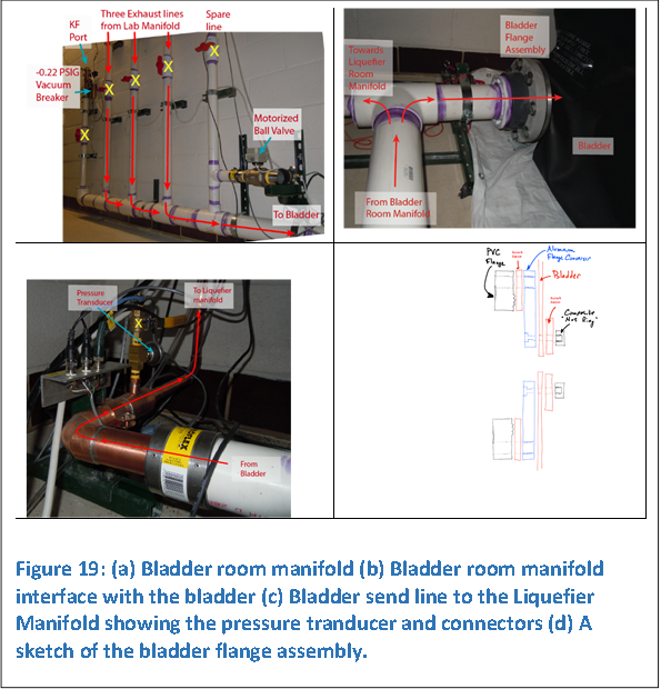
As shown in Figure 19, three helium exhaust lines from the Laboratory Manifold are merged into a 3” diameter PVC pipe. The flow is then directed into the helium recovery bladder and the liquefier manifold.
The large diameter pipe ensures that pressure pulses from pumping on helium reservoirs in the laboratory do not propagate back to sensitive (bolometer) IR detector helium reservoirs. The low impedance line couples to an atmospheric bladder, further minimizing pulses.
A spare line is available for future connections to other laboratory spaces. An extra KF access port is available. A -0.22 PSIG high-flow vacuum breaker ensures the bladder is not be damaged by accidental evacuation. Also, a nylon rope is tied down inside the 3” pipe near the flange assembly and thrown into the helium recovery bladder. The rope prevents the bladder from sealing against itself across the flange opening while inadvertently pumping.
A pressure transducer is located near the flange assembly used as part of an active interlock preventing underinflation of the bladder. A computer controlled motorized ball valve opens if the bladder becomes overinflated (bladder switches activated) or underinflated (the pressure inside the bladder is too low).
 The
bladder is approximately 3600 cu ft in volume (a capacity equivalent to 135
LLHe), providing a ballast in the system. No company that manufactures helium
bladders qualifies leak rates. A few report the bulk permeability of the
material.
The
bladder is approximately 3600 cu ft in volume (a capacity equivalent to 135
LLHe), providing a ballast in the system. No company that manufactures helium
bladders qualifies leak rates. A few report the bulk permeability of the
material.
AeroTech Laboratories (ATL) fabricated four small test bladders that we qualified in our lab. The measured leak rates of the 0.040” thick rubberized polyurethane matched the estimated bulk permeability rates. The rate of diffusion of helium through the test bladder extrapolate to about 15 LLHe/year for the surface area of our large bladder.
A 3” diameter pipe interfaces with the bladder via a PVC flange as shown in Figure 19. A custom aluminum flange converter is sandwiched between the bladder and a stock PVC flange. An ATL composite “nut ring” clamps the bladder to the flange converter. The assembly is sketched in Figure 19.
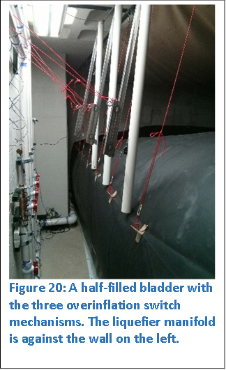
As shown in Figure 20, three switches mounted on three PVC bumpers press against hanging steel paddles when the bladder becomes over-inflated. If any two of the three switches are activated (closed), a relief valve is opened.
Great effort was expended to ensure that the bladder is not abraded or punctured in the entire room. All the surfaces exposed to the bladder were made smooth, including the electrical panels, plumbing, ducts, switches, shelving etc.. All walls were scraped to remove rough and sharp protrusions, and heavy paint and spackle smoothed out any remaining rough areas. The rough concrete ceiling was covered with a suspended tarp. The floor is covered with protective tarp. The bladder is suspended half-way up the bladder to ensure full deflation. Two PVC pipes are strapped to two top edges of the bladder to help minimize wrinkling during the deflation process. The rubber bladder is damaged when creased (you can see it begin to crack), so do not step on or pinch the bladder. Entry into the room must be performed with care to avoid damage to the bladder from rolling underneath the door.
The largest amount of stress occurs near the flange. When the bladder is fully inflated as was performed with air inflation tests using a blower motor, quite a bit of force was observed at the flange area due to bulging of the bladder. An effort was made to tie down the corner in way to alleviate some of the stresses.
To minimize creasing of the bladder, inflation/deflation tests showed that the pvc pipes tied along two edges provided enough weight to prevent undue folding of the top of the bladder upon deflation. Also, the pipes provide more reproducible inflation permitting installation of overinflation switches.
Current measured bladder loss rate is 0.5 LLHe/day. The measurement of losses were performed in two ways: (1) a known volume of helium gas was injected into the bladder while performing time-lapse photography. The pictures are correlated to a known amount of helium. Barometric pressure and temperature changes were taken into account. The slow loss integrated over many days is translated into a gas volume. (2) After recording this estimated loss, a known volume of gas was slowly re-injected into the bladder over the course of many hours. The pressure in the cylinder was recorded with the time. The closest picture that matched the initially filled condition of the bladder was then correlated to the loss of pressure in the cylinder.
The flange assembly is suspected to leak. I could not locate the leak with a helium sniffer probe. I would recommend coating the outside area of the bladder with silicone grease to attempt to seal the leak. Also, removing the composite nut ring and replacing with a larger-area backing ring inside the bladder would allow a larger diameter seal. Pressure intensifier rings at the larger diameter may do the trick.
PVC pipe is used to reduce cost. The solid-core PVC pipe is rated to many 10’s of PSI, but warnings from manufacturers state that you should never pressurize PVC pipe with gas. The compressed air inside the pipe, contrary to incompressible water pressure tests, can explode if the pipe fails at some point. The plastic pipe tends to splinter into dangerous shards. I find it odd that the internet is full of people making air pressurized guns and launchers from PVC pipe despite warnings. I pressurized the system to 10 PSI to test for leaks late in the evening when no one was around. Out of all the PVC joints, none of them leaked. The method of cleaning, using solvent (primer), and then gluing (cement) as instructed by the manufacturer is nearly full proof. Joining plastic to copper or steel pipe is done utilizing a ProFlex coupler, a rubber seal with a compression collar. These type of fittings are not rated to very high pressures but are fine for helium recovery and leak tight.
 A
Dahua DH-IPC-HFW4300S IP camera is installed in the bladder room (see
Appendix 6). The camera provides an estimate of the helium level. It is
accessible on Android and Windows systems. I use ISpy software on Windows and
the Dahua App on my Android phone. The liquefier computer is configured to
capture a picture every hour. This is useful for assessing leak rates of the
bladder.
A
Dahua DH-IPC-HFW4300S IP camera is installed in the bladder room (see
Appendix 6). The camera provides an estimate of the helium level. It is
accessible on Android and Windows systems. I use ISpy software on Windows and
the Dahua App on my Android phone. The liquefier computer is configured to
capture a picture every hour. This is useful for assessing leak rates of the
bladder.
Time lapsed photography has also been instrumental in tuning the inflation/deflation of the bladder with minimal creasing.